Before the advent of business process management systems (BPMS), there was a clear distinction between business process modeling and BPM application design. “Modeling” involved a set of tools for business analysts used to discover, diagram, analyze, and optimize business processes, often in concert with some formal methodology. The ultimate output of this effort, if used to create an automated BPM solution at all, served mainly as a “requirements document” that would (hopefully) be referenced by IT in the solution specification and design.
Modeling and the Third Wave
The BPMS idea, as introduced by books like Smith and Fingar’s Business Process Management – The Third Wave, called into question the value of this dichotomy, notorious for long deployment cycles and imperfect translation of business requirements into the resulting automated IT solution. The essential promise of BPMS, a combination design tool and runtime engine that can actually execute suitably designed process models, was to break down the business/IT divide and improve agility by accelerating the process improvement lifecycle. The key to this was to be a set modeling standards sufficiently simple and graphically intuitive that business analysts could use them, yet expressive and precise enough to be executed on a process engine.
Two key standards emerged from Business Process Management Initiative (BPMI) established to promote this BPMS idea: the Business Process Modeling Language (BPML), a standardized XML syntax and vocabulary for defining executable processes based on web service orchestration; and the Business Process Modeling Notation (BPMN), a diagramming standard for business analysts, initially envisioned as the graphical front end to BPML. However, in the marketplace BPML was quickly “trumped” by a similar proposal by IBM, Microsoft, and BEA, the Business Process Execution Language (BPEL), now an OASIS standard.
BPMN, left on its own so to speak, wandered off in a somewhat altered direction, focused on creating a standard look and feel for process diagrams that is more “business-friendly” than the UML diagrams used by IT. By standardizing the semantics of things like tasks, subprocesses, and events, and linking each to specific graphical shapes, icons, and line styles in the process diagram, BPMN allows business analysts to understand a process diagram regardless of which vendor’s modeling tool created it, and conversely to create process diagrams that other analysts can immediately understand without special training. While the BPMN spec suggests mappings of certain shapes and patterns to specific BPEL code, it’s been watered down a bit from the original vision of a standard business-friendly front end for executable process models.
BPMN in a Nutshell
For those unfamiliar with it, here is BPMN in a nutshell. Diagrams are essentially flowcharts. Process participants are defined by pools, which may be subdivided into swimlanes, as in many other modeling notations. From the perspective of the executable model, each pool represents a BPEL process. In addition, blank but named pools can also be used to represent external services or partner business processes for which the internals are opaque, a black box. A single business process diagram can be composed of multiple pools, meaning multiple executable processes.
The basic units of a process are tasks, subprocesses, and events. Subprocesses and tasks are represented by rectangles, events by circles. Various icons within those shapes indicate the particular type of event or subprocess. Subprocesses may either be embedded in the calling process or launched as an independent process, running in parallel with the calling process, and synchronizing with it via messages. Solid lines called sequence flows interconnect the tasks, subprocesses, and events within a single pool. Each sequence flow may be conditional or unconditional. In addition, BPMN offers a diamond Gateway shape that, depending on its icon, can be used for branching, splits, conditional splits, merges, or synchronizing joins.
So far this is very much like the usual workflow flowchart. But BPMN goes further in two important ways. First, in addition to sequence flows within a pool, BPMN shows message flows exchanged between pools. These indicate the signals the process engine uses to communicate with invoked services and partner processes. They are optional in the BPMN diagram, but are extremely useful for translating the diagram into real-world executable solutions.
Second, BPMN explicitly shows events, actions triggered by a signal of some sort, such as receipt of a message, expiration of a timer, detection of an error, etc. Each event has a trigger and a resulting action. The various types of triggers and resulting actions are indicated by the placement of the event in the diagram along with its internal icon. Generally speaking, events shown with an incoming sequence flow mean that the process issues the event (i.e., sends the message, waits for a time delay, or throws the error), and those with no incoming sequence flow mean that its outgoing sequence flow is triggered by the event (e.g., receipt of a message, timeout, or exception). Events of the second type placed on the border of a task, subprocess, or pool indicate that the normal flow within that task, subprocess, or pool is to be interrupted and the exception flow connected to the event is to be triggered. Already completed tasks within a process interrupted in this way are reversed by compensation actions defined by a compensation event linked to the task. Thus with BPMN events, exception-handling behavior and inter-process communications critical to the executable implementation are shown explicitly in the diagram, without requiring the modeler to specify the underlying technical details.
From BPMN to Executable Process
Today, BPMN is supported by enterprise architecture tools like Popkin System Architect and Casewise Corporate Modeler, which are trying to provide a shared modeling environment for IT architects and business analysts. These tools provide a broad multi-dimensional modeling environment, beyond process flow – organizational roles, resource models, data models, mapping to physical systems, etc. – and advanced simulation and analytics, but do not create executable processes. Some of them are beginning to offer translation of BPMN to BPEL, which can then be imported into the native design tool of a BPMS.
Even though those tools generally feature some kind of graphical flow design, the look and feel of process models built in the native BPMS environment vary so much between one tool and the next that a user trained in one would be hard pressed to understand his own process drawn in another tool. Moreover, designing executable processes is still considered an IT responsibility, and BPMS vendors – particularly those focused on BPEL and service-oriented architecture – are not yet ready to hide its inherent complexity just to help business analysts.
Meanwhile, the vast majority of business analysts continue to draw their business process diagrams the old fashioned way – in Microsoft Visio. It’s a tool they know, and it doesn’t require them to install an enterprise architecture suite or a developer IDE like Eclipse just to draw process diagrams. So here’s a bright idea: why not provide the BPMN standard shapes and icons as a Visio add-in? BPMN would at least add a level of common graphical semantics and potential reuse. That’s fairly obvious, and a few companies offer it today. But as long as we’re dreaming, let’s dream big. How about a BPMN add-in to Visio that generates executable BPEL? That would be the original Third Wave idea magically brought back to life!
Well, it’s here. For the past few days I’ve been using Process Modeler for Visio from a Swiss company ITP-Commerce. Process Modeler 2.1 not only provides a complete palette of BPMN shapes and icons, but allows you to annotate them to generate BPEL code that can be deployed on any BPEL-based process engine. Process Modeler allows business analysts to create BPMN diagrams in Visio, validate them, and then export them in BPEL. The BPEL models can then be loaded into a BPMS native design environment for completion of detailed design, testing, and deployment.
A future Process Modeler update will also allow the BPMN to generate XPDL, an alternative to BPEL based on the Workflow Management Coalition’s reference model. (While the industry analysts never talk about it, XPDL is actually the foundation of many more BPMS products than BPEL today.) Whether with BPEL or XPDL, Process Modeler brings business analysts directly into the BPM solution design process, not simply as authors of business requirements but active participants in the process improvement lifecycle.
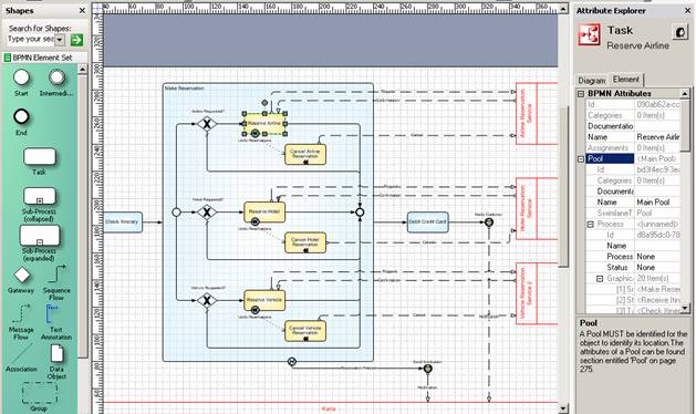
So how well does it work? If simply creating valid BPMN diagrams is the objective, it’s an absolute gem. You just drag and drop Pools, Tasks, Subprocesses, and Events from the BPMN Shape palette and connect them with Sequence Flows and Message Flows. Process Modeler knows all BPMN’s internal validation rules, and provides the analyst with a real-time ToDo List noting any problems in the diagram.
The resulting diagrams are typically easier to understand than the native BPEL diagrams created in BPMS designers. For example, multiple processes (BPMN “pools”) can coexist in a single business process diagram, something not found in BPEL designers. Each task or subprocess in the diagram can optionally be annotated with explanations, data and document flows, and other BPMN artifacts. “Collapsed” subprocesses, shown as a single rectangle in the parent diagram, are linked to an exploded view in a child diagram on another page. Process Modeler makes creative use of the BPMN Link event to interconnect portions of a process diagram spread over multiple Visio pages. In the end, Process Modeler can create extensive documentation of the process in Word and Excel.
The real magic, however, is in the BPEL export. Process Modeler currently generates a supplementary file that simplifies import into Oracle BPEL Designer, the design component of what is certainly the most complete BPEL-based BPMS today (and it’s available as a free download from www.oracle.com). Future versions of Process Modeler (projected for Q3 of this year) will support round-trip communications between Oracle BPEL and Process Modeler for Visio.
BPEL Export from BPMN requires the analyst to “instrument” the diagram. Each BPMN task that will be implemented as a “service” (i.e., BPEL invoke) is instrumented simply by linking it to a WSDL file. Of course, this assumes that the WSDLs have already been generated and made accessible by IT. If they have not, Process Modeler will generate default values for the required BPEL artifacts (partnerLinks, portTypes, messages, variables, etc.). This allows the model to be imported into Oracle BPEL Designer (or another BPMS design environment), where the default values will be changed to real ones.
Transforming BPMN process data to BPEL works slightly less smoothly. Process Modeler translates BPMN properties and message links into BPEL variables and their corresponding message types, but the variable naming scheme is awkward and not well-matched to Oracle. (Actually, this problem is more a result of BPMN’s suggested BPEL name mappings than Process Modeler.) On balance, it may still be easier to work with process variable assignments in Oracle BPEL Designer than in the current version of Process Modeler. It’s still a work in progress, but continually getting better.
All in all, Process Modeler for Visio is a giant step forward. Built for business analysts, not IT, it leverages a familiar drawing environment, creates process diagrams in a standards-compliant notation (complete with events, message flows, and other advanced constructs), generates complete documentation, and can be validated and exported as skeleton BPEL to real BPMS. It’s definitely worth an evaluation.


