This is the first article in a 4-part series presented by the BAInstitute.org.
For many new business and IT professionals entering the field of Business Architecture (BA), an exciting opportunity is at hand. However, these new entrants must consider beginning their career expanding endeavors with a clear and solid foundation in architecture principles. In this article, the reader is asked to participate in a visualization exercise in order to understand real Business Architecture in action.
A great place to start explaining and understanding architecture is with Business Process Modeling (BPM). Most business and IT professionals are very familiar with BPM as well as the Business Process Modeling and Notation (BPMN)[1]. In Figure 1, a few BPMN basic modeling elements along with their descriptions are illustrated. In order to create a typical low-level workflow model using the enterprise’s BPM software, one will select from the BPMN template, for example, a Task element, placing it into a BPM workflow model and assigning it a formal name, such as Do 1st Task. And then selecting for example, a Data Store element, placing it into the BPM model and also assigning it a formal name, such as Info A, and so on, eventually completing a generic workflow model such as the one depicted in Figure 2. All the formally named elements, Do 1st Task, Info A and others are used to create a generic composite model illustrating a typical workflow as shown in Figure 2.

Figure 1. Examples of BPMN Basic Modeling Elements
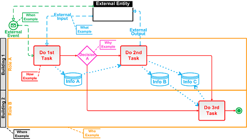
Figure 2. Generic Composite Workflow Model with Formally Named Elements
In this visualization, the reader is asked to IMAGAINE a Business Architecture software tool different from a BPM software tool. To begin with, there is no BPMN template with all the generic basic modeling elements as illustrated in Figure 1. However, every formally named, defined and operationally current element, such as Do 1st Task and Info A, are kept in an enterprise template according to a classification schema. All elements in the enterprise template are classified into one of six categories–WHAT, HOW, WHERE, WHO, WHEN and WHY. These categories are referred to as interrogatives. With this well-managed enterprise template of established, verified, normalized (e.g. redundancies eliminated) and fully integrated elements, anyone can build a workflow using previously defined and formally named elements. Along with enterprise wide availability, reuse of the formally named elements is optimized. And when necessary, new formally named elements or primitives are added as desired.
Consider that the generic swim lane workflow model illustrated in Figure 2 simply represents “some THINGS (e.g. Info A, the WHAT) transformed by some PROCESSES (e.g. Do 1st Task, the HOW) in some LOCATIONS (e.g. Building 1, the WHERE) by some PEOPLE (e.g. Role A, the WHO) at some TIME (e.g. External Event, the WHEN) for some REASONS (e.g. Decision A, the WHY).”[2] Obviously, the enterprise template of formally defined elements is quite extensive; these elements are also basic, fundamental and primitive—not capable of further decomposition, reduction or derivation. Logically, it follows that if something is not primitive, then it is a composite which is made of several things or multiple things.
In a metaphorical context, these primitives or formally defined elements are just like those found in Mendeleev’s Periodic Table of elements. For example, hydrogen and oxygen are both examples of atoms—primitive elements—found in Mendeleev’s Periodic Table. In their natural state on earth, each is a gas, but when combined to form water—a composite molecule made of two hydrogen atoms and one oxygen atom or H2O—it is found on earth mostly as a liquid, but also as a solid and a gas. Obviously, water is not found in Mendeleev’s Periodic Table of elements since it is a composite molecule consisting of two different primitive elements. The behavior of these two different gaseous atoms is independent from one another and of the water molecule as well. All atoms are unique in Mendeleev’s Periodic Table of elements and found only once, however, not unique in the numerous composite molecules such as water, in which they are found on earth and in the universe.
In the same context, the behavior of the enterprise’s primitives or formally defined elements is independent from one another and independent of their physical implementation. Each primitive is therefore, unique in the enterprise and normalized, but not unique as to how it is implemented in the enterprise. To see a manifestation of the visualization just described, the reader is asked to click on the following PowerPoint animation loaded out on youtube to see the creation of a workflow model from the enterprise template of primitives or formally defined elements of the enterprise. The animation runs less than 45 seconds.
As just illustrated in the youtube video, this architectural example uses formally defined enterprise-wide elements to create a generic and typical low-level workflow model. The elements are primitive, operationally current and available from the enterprise template to quickly build low-level workflows. Each primitive is selected and “appropriately connected” to other primitives until the user has completed assembling the desired workflow. As an example, the appropriate connectivity between two different tasks is defined by their shared inputs/outputs and represented in a primitive single variable model; the singe variable in this example is a task. “Appropriately connected” means that the primitive relationships between, for example, Do 1st Task and Do 2nd Task are defined by their shared inputs/outputs; which describe how one task relates to another. “Appropriately connected” also means that one must understand the primitive, its context with other primitives and how it is used with other primitives. Obviously, one would not connect a payroll task to a shipping task or expect a recruiting task to create some inventory info; this makes no sense as these relationships are illogical! And the BA software tool would prevent these irrational connections, but allow the “appropriate connection” between Do 1st Task and Do 2nd Task.
The manifestation of each individual element that appears in Figure 2 is based on the formally named element’s or primitive’s design specifications. Obviously, the design specification—the primitive model—is stored in the enterprise template, and is NOT an inventory of physical things. These formally defined elements or primitives, their “appropriate connectivity” and context with other primitives represent examples of engineering and design artifacts; and the dynamically assembled workflows represent examples of manufacturing and production artifacts.
At this point in time, the reader is probably asking, “but how does one create the enterprise template of primitives or formally defined enterprise wide elements so that each is available for reuse across the enterprise?” That answer and its supported animation are available in the next article in this 4-part series scheduled for publication on September 13, 2016.
References and Footnotes:
1.Object Management Group (OMG), “Documents Associated with Business Process Model and Notation (BPMN) Version 2.0,” Release date: January 2011. Download at http://www.omg.org/spec/BPMN/2.0/
2.See links.enterprisearchitecture.dk/links/files/Arch_Artifacts_versus_Applic_Dev_Artifacts.pdf Zachman, John A., ”Architecture Artifacts Vs Application Artifacts.” Zachman International, 2000.


